In this topic we will configure OSPF, verify and troubleshoot using show commands and what kinds of problems we can expect and how we can resolve these.
I have made some changes to our switch diagrams and added a couple of routers and re-jigged things around:

To enable OSPF we first need to enable the routing protocol:
configure terminal
router ospf 1
The value 1 is the instance number, this can be anything between 1 and 65535. Next we need to let the routing process know which networks we want to advertise, for example:
network 192.168.0.1 0.0.0.255 area 0
OSPF uses inverse (wildcard) subnet mask. The 0’s mean we want this part of the IP to exactly match (192.168.0.) and the last octet 255 means it can be any value. Area 0 is the backbone area for OSPF. I have kept this simple.
We can stop OSPF hellos being sent out of an interface using the passive-interface command. This can be useful on FastEthernet links that are connected to a switch network that do not need to receive routing updates. Sending routing updates to unnecessarily links can waste bandwidth and CPU resources also enhances security.
configure terminal
router ospf 1
passive-interface FastEthernet0/0
Below are the outputs of the commands for each device needed to make the diagram above fully functional:
RouterA:
configure terminal
interface FastEthernet 0/0
no shutdown
interface FastEthernet0/0.10
encapsulation dot1Q 10
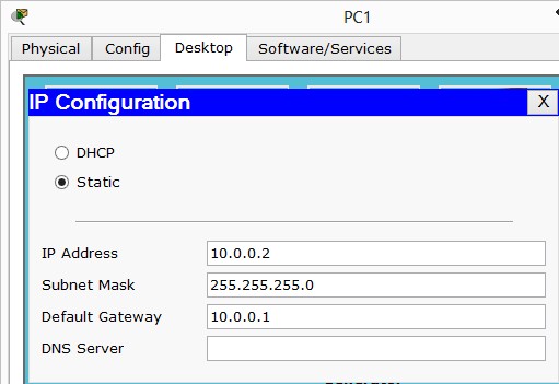
ip address 10.0.0.1 255.255.255.0
interface FastEthernet1/0
no shutdown
interface FastEthernet1/0.50
encapsulation dot1Q 50
ip address 10.0.3.33 255.255.255.224
interface Serial0/0
ip address 10.0.3.73 255.255.255.252
interface Serial0/1
ip address 10.0.3.70 255.255.255.252
router ospf 1
network 10.0.3.68 0.0.0.3 area 0
network 10.0.3.0 0.0.0.127 area 0
network 10.0.3.72 0.0.0.3 area 0
network 10.0.0.0 0.0.0.255 area 0
passive-interface FastEthernet 0/0
passive-interface FastEthernet 1/0
RouterB:
configure terminal
interface FastEthernet0/0
no shutdown
interface FastEthernet0/0.20
encapsulation dot1Q 20
ip address 10.0.1.1 255.255.255.0
interface FastEthernet1/0
no shutdown
interface FastEthernet1/0.40
encapsulation dot1Q 40
ip address 10.0.3.1 255.255.255.224
interface Serial0/0
ip address 10.0.3.66 255.255.255.252
interface Serial0/1
ip address 10.0.3.69 255.255.255.252
clock rate 64000
router ospf 1
network 10.0.1.0 0.0.0.255 area 0
network 10.0.3.64 0.0.0.3 area 0
network 10.0.3.0 0.0.0.127 area 0
network 10.0.3.68 0.0.0.3 area 0
passive-interface FastEthernet 0/0
passive-interface FastEthernet 1/0
RouterC:
configure terminal
interface FastEthernet0/0
no shutdown
interface FastEthernet0/0.30
encapsulation dot1Q 30
ip address 10.0.2.1 255.255.255.0
interface Serial0/0
ip address 10.0.3.74 255.255.255.252
clock rate 64000
interface Serial0/1
ip address 10.0.3.65 255.255.255.252
clock rate 64000
router ospf 1
network 10.0.2.0 0.0.0.255 area 0
network 10.0.3.72 0.0.0.3 area 0
network 10.0.3.64 0.0.0.3 area 0
passive-interface FastEthernet0/0
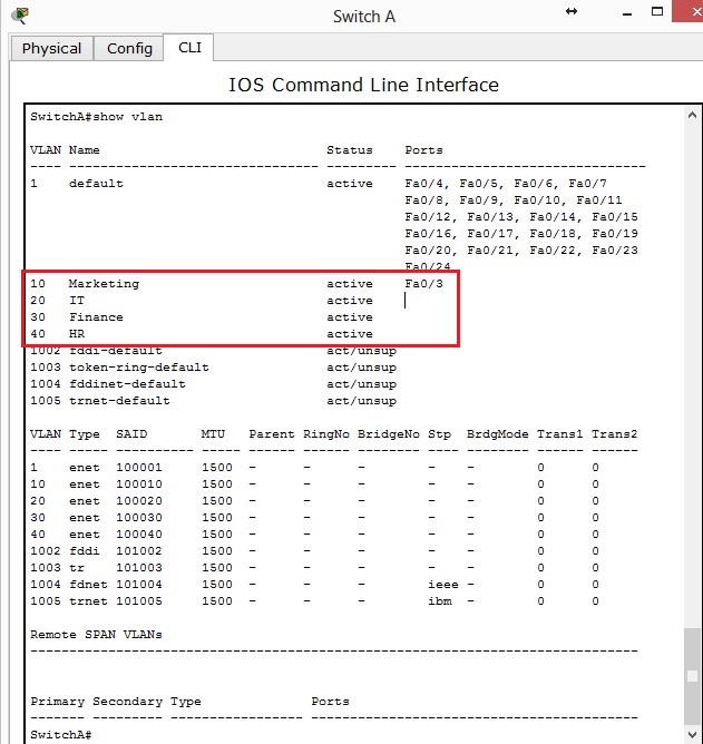
SwitchA:
configure terminal
spanning-tree mode rapid-pvst
interface FastEthernet0/1
switchport mode trunk
interface FastEthernet0/2
switchport access vlan 10
switchport mode access
spanning-tree portfast
interface range FastEthernet0/3-24
switchport mode access
spanning-tree portfast
SwitchB:
configure terminal
spanning-tree mode rapid-pvst
interface FastEthernet0/1
switchport mode trunk
interface FastEthernet0/2
switchport access vlan 20
switchport mode access
spanning-tree portfast
interface range FastEthernet0/3-24
switchport mode access
spanning-tree portfast
SwitchC:
configure terminal
spanning-tree mode rapid-pvst
interface FastEthernet0/1
switchport mode trunk
interface FastEthernet0/2
switchport access vlan 30
switchport mode access
spanning-tree portfast
interface range FastEthernet0/3-24
switchport mode access
spanning-tree portfast
SwitchD:
configure terminal
spanning-tree mode rapid-pvst
interface FastEthernet0/1
switchport mode trunk
interface FastEthernet0/2
switchport access vlan 50
switchport mode access
spanning-tree portfast
interface Range FastEthernet0/3-24
switchport mode access
spanning-tree portfast
SwitchE:
configure terminal
spanning-tree mode rapid-pvst
interface FastEthernet0/1
switchport mode trunk
interface FastEthernet0/2
switchport access vlan 40
switchport mode access
spanning-tree portfast
interface Range FastEthernet0/3-24
switchport mode access
spanning-tree portfast
OSPF by default uses the highest IP address for its routing process ID. The routing process ID is used to elect DR and BDR as well as advertise routes. For this reason, it may be a good idea to create a loopback interface to override this to ensure that becomes RID, Cisco even suggests using loopbacks.
Configuring a loopback is easy, lets do this on RouterC:
configre terminal
interface loopback 1
ip address 192.168.0.1 255.255.255.0
This doesn’t automatically make the RID become 192.168.0.1 we must either reload the router – Which could be inconvenient in a live environment or we can using the command router-id 192.168.0.1 to force the change.
configure terminal
router ospf 1
router-id 192.168.0.1
We can advertise default routes via the default-information originate command under the OSPF configuration. We can also use default-information originate always (not supported in Packet Tracer) – This advertises a default route even if one doesn’t exist, it will generate one and advertise this. To create a default route:
configure terminal
ip route 0.0.0.0 0.0.0.0 s0/1
Verify OSPF
Lets first begin by checking the RID of RouterC – We can verify this by using the show ip ospf command on RouterC:

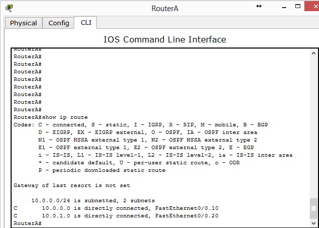
We can check OSPF routes via the show ip route command:

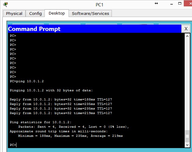
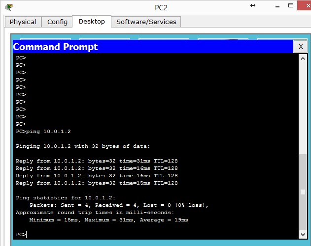
We can verify WAN connectivity by pinging each PC from each other. I’m going to demonstrate PC3 pinging PC1:

show ip osfneighbor will show information about all neighbors:

show ip ospf interface s0/0 will display information about the interface state whether it is up and OSPF information such as timers, what area the interface is in and network type.

Troubleshoot OSPF
- Ensure you’re using a wildcard mask and not a subnet mask when configuring OSPF
- Check IP addressing and subnet masks are correctly configured on WAN links
- Serial interfaces with a DCE cable attached must be configured with the clock rate command
- Routers running OSPF must have the same hello and dead timers to form a adjacency
- If using OSPF authentication must be match on other routers
- You may have accidentally configured passive-interface on a Serial interface running OSPF – this will stop advertisements
- debug ip ospf adj – shows elections for DR and BDR
- debug ip ospf packet – shows ospf hello packets being received by the router
- debug ip ospf hello – shows more in depth information relating to hello packets including being sent and received by the router
You can download the Packet Tracer file here:
[wpfilebase tag=fileurl id=1 linktext=’Download Packet Tracer OSPF configuration’ /]


