In this topic I will discuss how to configure interVLAN routing typically known as Router on a Stick.
This is the setup we will be working with in packet tracer:

Notice that PC1 and PC2 are in different VLANs and different IP subnets. We are going to allow them to communicate with each other via Router A.
First we are going to configure the trunk links between each of the switches and between switch C and Router A. I will use the range command to save keep typing the individual interfaces.
Switch A
configure terminal
interface range fa0/1-fa0/2
switchport mode trunk
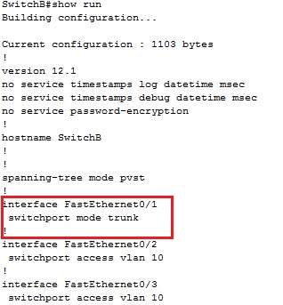
Switch B
configure terminal
interface range fa0/1-fa0/2
switchport mode trunk
Switch C
configure terminal
interface range fa0/1-fa0/3
switchport mode trunk
We will come back to Router A a little later on to finish the trunk configuration.
We need to configure the access ports and VLANs between the switches connected to PCs.
Switch A:
configure terminal
interface fa0/3
switchport access vlan 10
Switch B:
configure terminal
interface fa0/3
switchpport access vlan 20
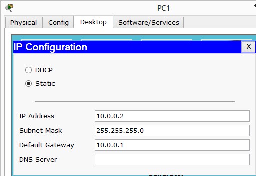
We will configure PC1 and PC2 with an IP address and default gateway.
PC1:
IP Address: 10.0.0.2
Subnet: 255.255.255.0
Default Gateway: 10.0.0.1

PC2:
IP Address: 10.0.1.2
Subnet: 255.255.255.0
Default Gateway: 10.0.1.1

If we try and ping PC2 from PC1 the result will fail. Why? Because there’s no way for VLAN 10 and VLAN 20 to communicate, Also they’re in different subnets.
To allow these two PCs to communicate we need to configure Router A to route frames between VLAN 10 and VLAN 20.
If you noticed we set default gateways on PC1 and PC2, we will now configure these on Router A. This way, when PC1 or PC2 wants to send a frame to a different subnet, it will forward to the default gateway, the default gateway will lookup to see if it has an entry in its routing table if it does, it will forward otherwise it will drop the frame.
We will configure two sub interfaces on Router A under fa0/0 one for VLAN 10 and one for VLAN20. First we need to bring up the fast ethernet 0/0 interface up, otherwise the sub interfaces once configured will not work.
Router A:
configure terminal
interface fa0/0
no shutdown
Now to configure the sub interfaces on Router A:
configure terminal
interface fa0/0.10
encapsulation dot1q 10
ip address 10.0.0.1 255.255.255.0
interface fa0/0.20
encapsulation dotq1 20
ip address 10.0.1.1 255.255.255.0
I tend to create sub-interfaces that match the VLAN number, this is handy when trying to troubleshoot as you can quickly identify which VLAN belongs to which sub-interface.
The encapsulation dot1q 10/20 command defines the sub interface as a trunk link and that it expects to send/receive VLAN 10/20 traffic on this interface.
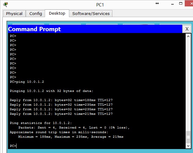
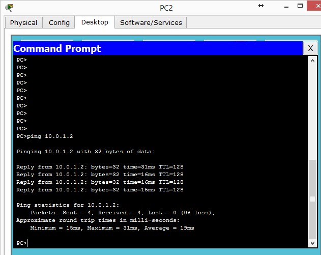
That’s pretty much it. If we try to ping PC2 from PC1 we should see a successful ping:

And from PC2 to PC1:

Verifying:
We verified that PC1 can communicate with PC2 above.
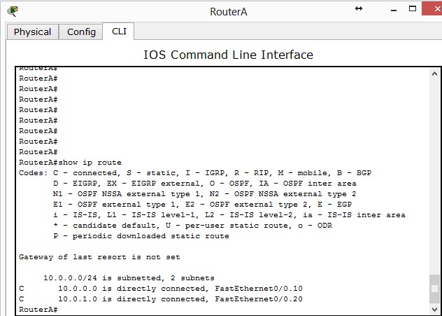
We can show the routing table on RouterA:

The above shows two directly connected routes, one for VLAN 10 and one for VLAN 20 this is how the router knows where to route to.
show running-config can be used on the switches and routers to ensure correct access VLAN assigned, trunk links are configured and correct IP addresses.
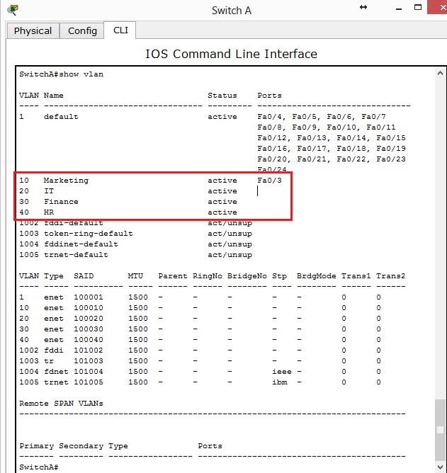
show vlan on the switches will show what VLANs are assigned to which ports.
Ping can we be used to verify connectivity, if you cant ping the destination IP, ensure you can ping your local default gateway and then destination gateway to try and figure where the problems lies.
Troubleshooting:
- Ensure the links between switches and routers are trunked
- Make sure PCs are in correct VLANs
- Make sure PCs have correct IP Subnet / Default Gateway addresses
- Use tracert on the PCs to see where the frames are failing
- Check the router to make sure has the correct sub-interfaces and they match the default gateway of the PCs
- The fast ethernet port on the router should be up (no shutdown) otherwise sub-interfaces will not work
- Correct cables must be used between PC and switch (straight through) switch to switch (crossover) and switch to router (straight through)


